Manual:System/Serial Console
Overview
Sub-menu: /system console, /system serial-terminal
Standards: RS-232
The Serial Console and Terminal are tools, used to communicate with devices and other systems that are interconnected via serial port. The serial terminal may be used to monitor and configure many devices - including modems, network devices (including MikroTik routers), and any device that can be connected to a serial (asynchronous) port.
The Serial Console feature is for configuring direct-access configuration facilities (monitor/keyboard and serial port) that are mostly used for initial or recovery configuration.
If you do not plan to use a serial port for accessing another device or for data connection through a modem, you can configure it as a serial console. The first serial port is configured as a serial console, but you can choose to unconfigure it to free it for other applications. A free serial port can also be used to access other routers' (or other equipment, like switches) serial consoles from a MikroTik RouterOS router. A special null-modem cable is needed to connect two hosts (like, two PCs, or two routers; not modems). Note that a terminal emulation program (e.g., HyperTerminal on Windows or minicom on linux) is required to access the serial console from another computer.
Several customers have described situations where the Serial Terminal (managing side) feature would be useful:
- on a mountaintop, where a MikroTik wireless installation sits next to equipment (including switches and Cisco routers) that can not be managed in-band (by telnet through an IP network)
- monitoring weather-reporting equipment through a serial port
- connection to a high-speed microwave modem that needed to be monitored and managed by a serial connection
With the serial-terminal feature of the MikroTik, up to 132 (and, maybe, even more) devices can be monitored and controlled.
Serial Console Configuration
A special null-modem cable should be used for connecting to the serial console from another computer. The Serial Console cabling diagram for DB9 connectors is as follows:
| Router Side (DB9f) | Signal | Direction | Side (DB9f) |
|---|---|---|---|
| 1, 6 | CD, DSR | IN | 4 |
| 2 | RxD | IN | 3 |
| 3 | TxD | OUT | 2 |
| 4 | DTR | OUT | 1, 6 |
| 5 | GND | - | 5 |
| 7 | RTS | OUT | 8 |
| 8 | CTS | IN | 7 |
Note that the above diagram will not work if the software is configured to do hardware flow control, but the hardware does not support it (e.g., some RouterBOARD models have reduced serial port functionality). If this is the case, either turn off the hardware flow control or use a null-modem cable with loopback, which will simulate the other device's handshake signals with it's own. The diagram for such a cable is as follows:
| Router Side (DB9f) | Signal | Direction | Side (DB9f) |
|---|---|---|---|
| 1, 4, 6 | CD, DTR, DSR | LOOP | 1, 4, 6 |
| 2 | RxD | IN | 3 |
| 3 | TxD | OUT | 2 |
| 5 | GND | - | 5 |
| 7, 8 | RTS, CTS | LOOP | 7, 8 |
Note that although it is recommended to have a 5-wire cable for this connection, in many cases it is enough to have 3 wires (for unlooped signals only), leaving both loops to exist only inside the connectors. Other connection schemes exist as well.
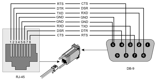
RJ45 type serial port
This type of port is used on RouterBOARD 2011, 3011, 4011, CCR1072, CCR1036 r2 and CRS series devices, sometimes called "Cisco style" serial port.

| Signal | Console Port (DTE) RJ-45 | RJ-45 Rolled Cable RJ-45 Pin | Adapter DB-9 Pin | Adapter DB-25 Pin | Signal |
|---|---|---|---|---|---|
| RTS | 1 | 8 | 8 | 5 | CTS |
| DTR | 2 | 7 | 6 | 6 | DSR |
| TxD | 3 | 6 | 2 | 3 | RxD |
| Ground | 4 | 5 | 5 | 7 | Ground |
| Ground | 5 | 4 | 5 | 7 | Ground |
| RxD | 6 | 3 | 3 | 2 | TxD |
| DSR | 7 | 2 | 4 | 20 | DTR |
| CTS | 8 | 1 | 7 | 4 | RTS |
RB M33G Aditional serial header
For RBM33G additional serial header can be attached on GPIO pins U3_RXD, GND, U3_TXD, and 3V3
CCR serial header
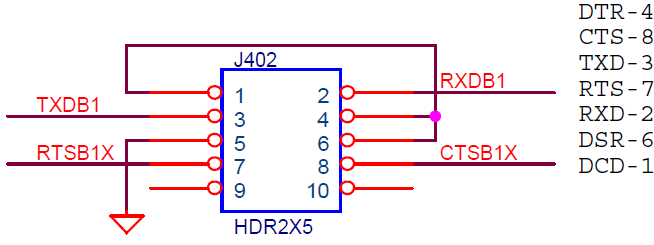
The Cloud Core Router series devices have a serial header on the PCB board, called J402 or 100
Here is the pinout of that connector:
Configuring Console
Sub-menu: /system console
Properties
| Property | Description |
|---|---|
| channel (integer (0..4294967295); Default: 0) | |
| disabled (yes | no; Default: no) | Whether serial console is enabled or not. |
| port (string) | Which port should the serial terminal listen to |
| term (string) | Terminal type |
Read-only properties
| Property | Description |
|---|---|
| free (yes | no) | Console is ready for use. |
| used (yes | no) | Console is in use. |
| vcno (integer) | number of virtual console - [Alt]+[F1] represents '1', [Alt]+[F2] - '2', etc.. |
| wedged (yes | no) | Console is currently not available |
Example
To disable all virtual consoles (available through the direct connection with keyboard and monitor) except for the first one:
[admin@MikroTik] system console> print
Flags: X - disabled, W - wedged, U - used, F - free
 #   PORT    VCNO       TERM
 0 F serial0            MyConsole
 1 U         1          linux
 2 F         2          linux
 3 F         3          linux
 4 F         4          linux
 5 F         5          linux
 6 F         6          linux
 7 F         7          linux
 8 F         8          linux
[admin@MikroTik] system console> disable 2,3,4,5,6,7,8
[admin@MikroTik] system console> print
Flags: X - disabled, W - wedged, U - used, F - free
 #   PORT    VCNO       TERM
 0 F serial0            MyConsole
 1 U         1          linux
 2 X         2          linux
 3 X         3          linux
 4 X         4          linux
 5 X         5          linux
 6 X         6          linux
 7 X         7          linux
 8 X         8          linux
[admin@MikroTik] system console>
To check the configuration of the serial port:
[admin@MikroTik] > port print detail
  0 name=serial0 used-by=Serial Console baud-rate=9600 data-bits=8 parity=none
    stop-bits=1 flow-control=none

  1 name=serial1 used-by="" baud-rate=9600 data-bits=8 parity=none stop-bits=1
    flow-control=none

[admin@MikroTik] >
To edit serial port settings, you have to use "/port edit" or "/port set"
Serial Cable
If your device has a Serial port, you can use a console cable (or Null modem cable)
Plug one end of the serial cable into the console port (also known as a serial port or DB9 RS232C asynchronous serial port) of the RouterBOARD and the other end in your PC (which hopefully runs Windows or Linux). You can also use a USB-Serial adapter. Run a terminal program (HyperTerminal, or Putty on Windows) with the following parameters for All RouterBOARD models except 230:
115200bit/s, 8 data bits, 1 stop bit, no parity, flow control=none by default.
RouterBOARD 230 parameters are:
9600bit/s, 8 data bits, 1 stop bit, no parity, hardware (RTS/CTS) flow control by default.
If parameters are set correctly you should be able to see login prompt. Now you can access router by entering username and password:
MikroTik 4.15
MikroTik Login:

  MMM      MMM       KKK                          TTTTTTTTTTT      KKK
  MMMM    MMMM       KKK                          TTTTTTTTTTT      KKK
  MMM MMMM MMM  III  KKK  KKK  RRRRRR     OOOOOO      TTT     III  KKK  KKK
  MMM  MM  MMM  III  KKKKK     RRR  RRR  OOO  OOO     TTT     III  KKKKK
  MMM      MMM  III  KKK KKK   RRRRRR    OOO  OOO     TTT     III  KKK KKK
  MMM      MMM  III  KKK  KKK  RRR  RRR   OOOOOO      TTT     III  KKK  KKK

  MikroTik RouterOS 4.15 (c) 1999-2010       http://www.mikrotik.com/


[admin@MikroTik] >
Detailed description of CLI login is in login process section.
Using Serial Terminal
Command: /system serial-terminal
The command is used to communicate with devices and other systems that are connected to the router via serial port.
All keyboard input is forwarded to the serial port and all data from the port is output to the connected device. Ctrl-A is the prefix key, which means that you will enter a small "menu" by pressing this combination of keys. The Ctrl-A character will not be sent to your device! If you need to send Ctrl-A character to remote device, press Ctrl-A twice. After exiting with Ctrl-A and then Q, the control signals of the port are lowered. The speed and other parameters of serial port may be configured in the /port directory of router console. No terminal translation on printed data is performed. It is possible to get the terminal in an unusable state by outputting sequences of inappropriate control characters or random data. Do not connect to devices at an incorrect speed and avoid dumping binary data.
| Property | Description |
|---|---|
| port (string; Default: ) | Port name to use |
The serial port to be used as a serial terminal needs to be free (e.g., there should not be any serial consoles, LCD or other configuration). Check the previous chapter to see how to disable serial console on a particular port. Use /port print command to see if some other application is still using the port.
Ctrl-A has a special meaning and is used to provide a possibility of exiting from nested serial-terminal sessions:
To send Ctrl-A to to serial port, press Ctrl-A Ctrl-A

Note: When rebooting a RouterBoard the bootloader (RouterBOOT) will always use the serial console (serial0 on RouterBoards) to send out some startup messages and offer access to the RouterBOOT menu. Having text coming out of the serial port to the connected device might confuse your attached device and get stuck on boot loader. To avoid this reconfigure RouterBOOT to enter the RouterBOOT menu only when a DEL character is received.
Example
To connect to a device connected to the serial0 port:
[admin@dzeltenais_burkaans] > /system serial-terminal serial0

[Ctrl-A is the prefix key]

[admin@R2] /ip address>
Console Screen
Sub-menu: /system console screen
This facility is created to change line number per screen if you have a monitor connected to router.
| Property | Description |
|---|---|
| line count (25|40|50; Default: 25) | Number of lines on monitor |
This parameter is applied only to a monitor, connected to the router.
Example
To set monitor's resolution from 80x25 to 80x40:
[admin@MikroTik] system console screen> set line-count=40
[admin@MikroTik] system console screen> print
    line-count: 40
[admin@MikroTik] system console screen>
See More
[ Top | Back to Content ]

