Manual:Multicast SPT Switchover: Difference between revisions
New page: =Multicast SPT switchover= ==Overview== For many receivers the route via RP may not be the best path to source. To obtain lower latencies, it is possible to initiate a transfer from the ... |
No edit summary |
||
| (12 intermediate revisions by 3 users not shown) | |||
| Line 1: | Line 1: | ||
{{Versions|v3, v4}} | |||
==Overview | __TOC__ | ||
<div class=manual> | |||
=Overview= | |||
For many receivers the route via RP may not be the best path to source. To obtain lower latencies, it is possible to initiate a transfer from the shared tree to a shortest-path tree (SPT). | For many receivers the route via RP may not be the best path to source. To obtain lower latencies, it is possible to initiate a transfer from the shared tree to a shortest-path tree (SPT). | ||
| Line 18: | Line 22: | ||
This is known as an (S,G,rpt) Prune. The Prune message travels hop-by-hop, instantiating state along the path towards the RP indicating that traffic from S for G should not be forwarded in this direction. By now, the receiver will be receiving traffic from S along the shortest-path tree between the receiver and S. | This is known as an (S,G,rpt) Prune. The Prune message travels hop-by-hop, instantiating state along the path towards the RP indicating that traffic from S for G should not be forwarded in this direction. By now, the receiver will be receiving traffic from S along the shortest-path tree between the receiver and S. | ||
=Configuration= | |||
For this configuration three routers will be used - R1,R2 and R3. Router R2 will be used as RP and multicast traffic will be send to address 224.1.1.10. | For this configuration three routers will be used - R1,R2 and R3. Router R2 will be used as RP and multicast traffic will be send to address 224.1.1.10. | ||
| Line 26: | Line 30: | ||
* Enable switchover option: | * Enable switchover option: | ||
<pre> | <pre> | ||
/routing pim switch-to-stp=yes switch-to-spt-bytes= | /routing pim switch-to-stp=yes switch-to-spt-bytes=102400 | ||
</pre> | </pre> | ||
* Add interfaces and RP: | * Add interfaces and RP: | ||
| Line 34: | Line 38: | ||
</pre> | </pre> | ||
There are two main options for SPT threshold - interval and bytes. From those two values bitrate threshold is calculated for switching from RP Tree to SP tree. | |||
* "switch-to-spt-interval" - measurement interval in seconds for measuring bitrate of traffic from multicast sender. Values greater than 10seconds are recommended (default value is 100s). | |||
* "switch-to-spt-bytes" - specifies maximum number of bytes from multicast sender that can be receibed in interval seconds. When threshold is exceeded, router will attempt to switch to SPT. If bytes are set to 0, then switch should happen immediately. | |||
In our example threshold is set to 1024 bytes/s | |||
=Testing= | |||
To test configuration, you can use VLC to launch multicast stream | To test configuration, you can use VLC to launch multicast stream | ||
| Line 50: | Line 60: | ||
SG_rpt 224.1.1.10 10.1.101.225 10.55.2.1 | SG_rpt 224.1.1.10 10.1.101.225 10.55.2.1 | ||
</pre> | </pre> | ||
</div> | |||
[[Category:Routing]] | |||
[[Category:Multicast]] | |||
[[Category:Examples]] | |||
Latest revision as of 17:15, 17 April 2018
Overview
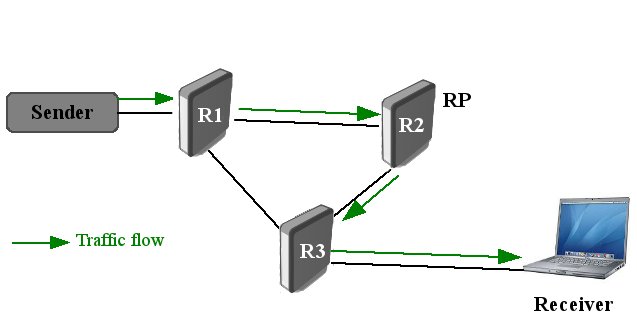
For many receivers the route via RP may not be the best path to source. To obtain lower latencies, it is possible to initiate a transfer from the shared tree to a shortest-path tree (SPT).
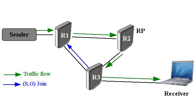
From diagram above it is obvious that traffic flow from sender to receiver through RP is not the best path. In this situation shortest-path tree (SPT) switchover comes to help. To initiate switchover, last-hop router sends an (S,G) join towards S and additional (S,G) state is created.
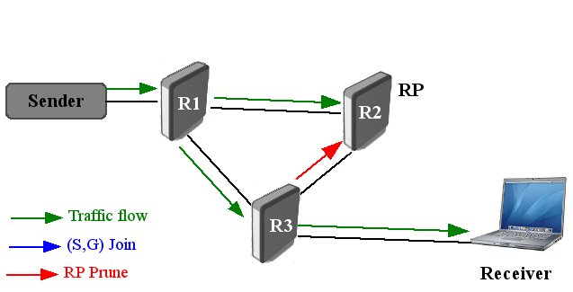
When join reaches S subnet or router that already has (S,G) state, data packets from S start to flow following the (S,G) state until they reach the receiver. Now receiver will be receiving two copies of the data - one from the SPT and one from the RPT. At this point additional (S,G) state is created along shared tree to prune off traffic through RP.
This is known as an (S,G,rpt) Prune. The Prune message travels hop-by-hop, instantiating state along the path towards the RP indicating that traffic from S for G should not be forwarded in this direction. By now, the receiver will be receiving traffic from S along the shortest-path tree between the receiver and S.
Configuration
For this configuration three routers will be used - R1,R2 and R3. Router R2 will be used as RP and multicast traffic will be send to address 224.1.1.10.
Configuration for all three routers are the same and is quite simple.
- Enable switchover option:
/routing pim switch-to-stp=yes switch-to-spt-bytes=102400
- Add interfaces and RP:
/routing pim interface add all
/rputing pim rp add address=<R2_IP_address>
There are two main options for SPT threshold - interval and bytes. From those two values bitrate threshold is calculated for switching from RP Tree to SP tree.
- "switch-to-spt-interval" - measurement interval in seconds for measuring bitrate of traffic from multicast sender. Values greater than 10seconds are recommended (default value is 100s).
- "switch-to-spt-bytes" - specifies maximum number of bytes from multicast sender that can be receibed in interval seconds. When threshold is exceeded, router will attempt to switch to SPT. If bytes are set to 0, then switch should happen immediately.
In our example threshold is set to 1024 bytes/s
Testing
To test configuration, you can use VLC to launch multicast stream Download it from [1] Simple streaming how-to: [2]
After the stream is launched you can check all PIM created join states.
/routing pim join print
Flags: RP - (*,*,RP), WC - (*,G), SG - (S,G), SG_rpt - (S,G,rpt)
       GROUP           SOURCE          RP
    WC 224.0.0.0       10.55.2.1       10.55.2.1
    SG 224.1.1.10      0.0.0.0         10.55.2.1
       224.1.1.10      10.1.101.225    10.55.2.1
SG_rpt 224.1.1.10      10.1.101.225    10.55.2.1


