Manual:Load balancing multiple same subnet links: Difference between revisions
No edit summary |
|||
| (6 intermediate revisions by 3 users not shown) | |||
| Line 1: | Line 1: | ||
{{Versions|v4}} | {{Versions|v4,v5}} | ||
<div class=manual> | <div class=manual> | ||
{{ Warning | Article is migrated to our new [https://help.mikrotik.com/docs/display/ROS/Firewall+Marking documentation]! }} | |||
<h2>Summary</h2> | <h2>Summary</h2> | ||
| Line 8: | Line 10: | ||
<h2>Application Example</h2> | <h2>Application Example</h2> | ||
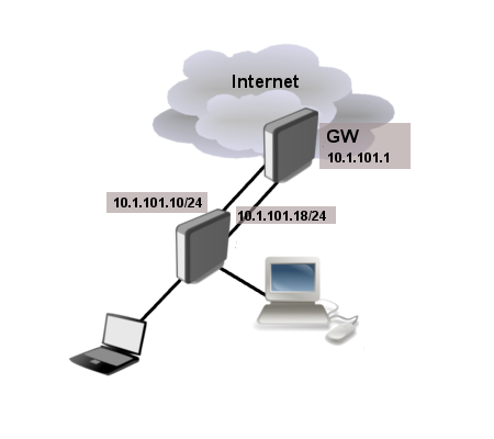
[[File:two-link-example.png]] | |||
<h3>Configuration</h3> | Provider is giving us two links with IP addresses from the same network range (10.1.101.10/24 and 10.1.101.18/24). Gateway for both of these links is the same 10.1.101.1 | ||
<h3>Configuration Example 1</h3> | |||
Here is the whole configuration for those who want to copy&paste | Here is the whole configuration for those who want to copy&paste | ||
| Line 31: | Line 35: | ||
/ip firewall mangle | /ip firewall mangle | ||
add action=mark-routing chain= | add action=mark-routing chain=prerouting src-address=192.168.1.0/24 new-routing-mark=first | ||
add action=mark-routing chain= | add action=mark-routing chain=prerouting src-address=192.168.2.0/24 new-routing-mark=other | ||
</pre> | </pre> | ||
| Line 38: | Line 42: | ||
<h4>IP address</h4> | <h4>IP address</h4> | ||
In previous RouterOS version multiple IP addresses from the same subnet on different interfaces were not allowed. Fortunately v4 allows such configurations. | In previous RouterOS version, multiple IP addresses from the same subnet on different interfaces were not allowed. Fortunately, from v4 RouterOS allows such configurations. | ||
In this example our provider assigned two upstream links, one connected to <b>ether1</b> and other to <b>ether2</b>. Our local network has two subnets 192.168.1.0/24 and 192.168.2.0/24 | In this example our provider assigned two upstream links, one connected to <b>ether1</b> and other to <b>ether2</b>. Our local network has two subnets 192.168.1.0/24 and 192.168.2.0/24 | ||
| Line 55: | Line 59: | ||
gateway-status=ether1 reachable,ether2 reachable distance=0 scope=10 | gateway-status=ether1 reachable,ether2 reachable distance=0 scope=10 | ||
</pre> | </pre> | ||
<h4>Mangle and NAT</h4> | <h4>Mangle and NAT</h4> | ||
| Line 64: | Line 66: | ||
<pre> | <pre> | ||
/ip firewall mangle | /ip firewall mangle | ||
add action=mark-routing chain= | add action=mark-routing chain=prerouting src-address=192.168.1.0/24 new-routing-mark=first | ||
add action=mark-routing chain= | add action=mark-routing chain=prerouting src-address=192.168.2.0/24 new-routing-mark=other | ||
</pre> | </pre> | ||
| Line 103: | Line 105: | ||
</pre> | </pre> | ||
Finally, we have one additional entry specifying that traffic from the router itself (the traffic without any routing marks) will be resolved in main routing table. | Finally, we have one additional entry specifying that traffic from the router itself (the traffic without any routing marks) will be resolved in the main routing table. | ||
<pre> | <pre> | ||
/ip route | /ip route | ||
| Line 111: | Line 113: | ||
[[Category:Unfinished]] | [[Category:Unfinished]] | ||
[[Category:Routing]] | [[Category:Routing|Loadbalancingmultiplesamesubnetlinks]] | ||
[[Category:Manual]] | [[Category:Manual|Loadbalancingmultiplesamesubnetlinks]] | ||
[[Category:Examples]] | [[Category:Examples|Loadbalancingmultiplesamesubnetlinks]] | ||
Latest revision as of 09:27, 14 April 2021

Warning: Article is migrated to our new documentation!
Summary
This example demonstrates how to set up load balancing if provider is giving IP addresses from the same subnet for all links.
Application Example
Provider is giving us two links with IP addresses from the same network range (10.1.101.10/24 and 10.1.101.18/24). Gateway for both of these links is the same 10.1.101.1
Configuration Example 1
Here is the whole configuration for those who want to copy&paste
/ip address
add address=10.1.101.18/24 interface=ether1
add address=10.1.101.10/24 interface=ether2
add address=192.168.1.1/24 interface=Local
add address=192.168.2.1/24 interface=Local

/ip route
add gateway=10.1.101.1
add gateway=10.1.101.1%ether1 routing-mark=first
add gateway=10.1.101.1%ether2 routing-mark=other

/ip firewall nat
add action=masquerade chain=srcnat out-interface=ether1
add action=masquerade chain=srcnat out-interface=ether2

/ip firewall mangle
add action=mark-routing chain=prerouting src-address=192.168.1.0/24 new-routing-mark=first
add action=mark-routing chain=prerouting src-address=192.168.2.0/24 new-routing-mark=other
IP address
In previous RouterOS version, multiple IP addresses from the same subnet on different interfaces were not allowed. Fortunately, from v4 RouterOS allows such configurations.
In this example our provider assigned two upstream links, one connected to ether1 and other to ether2. Our local network has two subnets 192.168.1.0/24 and 192.168.2.0/24
/ip address
add address=10.1.101.18/24 interface=ether1
add address=10.1.101.10/24 interface=ether2
add address=192.168.1.1/24 interface=Local
add address=192.168.2.1/24 interface=Local
After IP address is set up, connected route will be installed as ECMP route
[admin@MikroTik] /ip route> print detail
 0 ADC  dst-address=10.1.101.0/24 pref-src=10.1.101.18 gateway=ether1,ether2
        gateway-status=ether1 reachable,ether2 reachable distance=0 scope=10
Mangle and NAT
In our example very simple policy routing is used. Clients from 192.168.1.0/24 subnet is marked to use "first" routing table and 192.168.2.0/24 to use "other" subnet.

Note: The same can be achieved by setting up route rules instead of mangle.
/ip firewall mangle
add action=mark-routing chain=prerouting src-address=192.168.1.0/24 new-routing-mark=first
add action=mark-routing chain=prerouting src-address=192.168.2.0/24 new-routing-mark=other
And masquerade our local networks
/ip firewall nat
add action=masquerade chain=srcnat out-interface=ether1
add action=masquerade chain=srcnat out-interface=ether2

Warning: You will also have to deal with traffic coming to and from the router itself. For explanations look at PCC configuration example.
IP route
We are adding two gateways, one to resolve in "first" routing table and another to "other" routing table.
/ip route
add gateway=10.1.101.1%ether1 routing-mark=first
add gateway=10.1.101.1%ether2 routing-mark=other
Interesting part of these routes is how we set gateway. gateway=10.1.101.1%ether1 means that gateway 10.1.101.1 will be explicitly reachable over ether1
[admin@MikroTik] /ip route> print detail
Flags: X - disabled, A - active, D - dynamic,
C - connect, S - static, r - rip, b - bgp, o - ospf, m - mme,
B - blackhole, U - unreachable, P - prohibit
 0 A S  dst-address=0.0.0.0/0 gateway=10.1.101.1%ether2
        gateway-status=10.1.101.1 reachable ether2 distance=1 scope=30
        target-scope=10 routing-mark=other

 1 A S  dst-address=0.0.0.0/0 gateway=10.1.101.1%ether1
        gateway-status=10.1.101.1 reachable ether1 distance=1 scope=30
        target-scope=10 routing-mark=first
Finally, we have one additional entry specifying that traffic from the router itself (the traffic without any routing marks) will be resolved in the main routing table.
/ip route
add gateway=10.1.101.1

