Manual:Interface/Gre: Difference between revisions
| Line 86: | Line 86: | ||
==Setup examples== | ==Setup examples== | ||
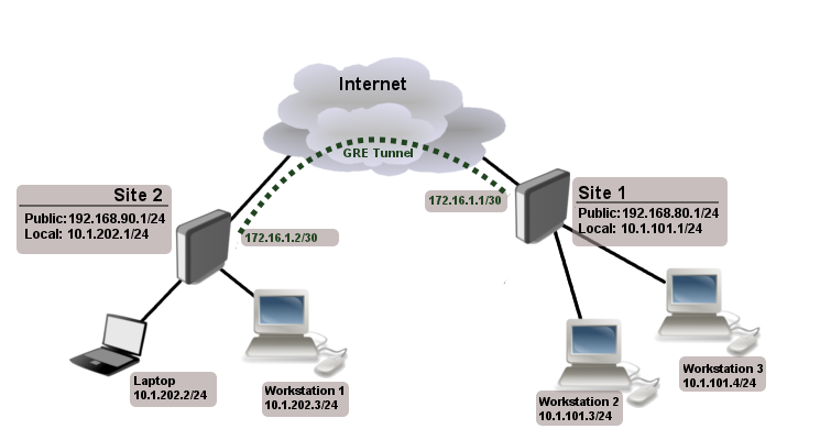
The goal of example is to get Layer 3 connectivity between two remote sites over the internet. | |||
[[File:site-to-site-gre-example.png]] | [[File:site-to-site-gre-example.png]] | ||
We two sites '''Site1''' with local network range 10.1.101.0/24 and '''Site2''' with local network range 10.1.202.0/24. | |||
First step is to create GRE tunnels. | |||
Router on site 1: | |||
<pre> | |||
/interface gre add name=myGre remote-address=192.168.90.1 local-address=192.168.80.1 | |||
</pre> | |||
Router on site 2: | |||
<pre> | |||
/interface gre add name=myGre remote-address=192.168.80.1 local-address=192.168.90.1 | |||
</pre> | |||
As you can see tunnel configuration is quite simple. | |||
{{ Note | In this example keepalive is not configured, so tunnel interface will have '''running''' flag even if remote tunnel end is not reachable }} | |||
Now we just need to set up tunnel addresses and proper routing. | |||
Router on site 1: | |||
<pre> | |||
/ip address | |||
add address=172.16.1.1/30 interface=myGre | |||
/ip route | |||
add dst-address=10.1.202.0/24 gateway=172.16.1.2 | |||
</pre> | |||
Router on site 2: | |||
<pre> | |||
/ip address | |||
add address=172.16.1.2/30 interface=myGre | |||
/ip route | |||
add dst-address=10.1.101.0/24 gateway=172.16.1.1 | |||
</pre> | |||
At this point sites have Layer 3 connectivity over GRE tunnel. | |||
{{Cont}} | {{Cont}} | ||
Revision as of 12:22, 16 August 2011
Summary
Sub-menu: /interface gre
Standards: GRE RFC 1701
GRE (generic routing encapsulation) is a tunneling protocol that was originally developed by Cisco. It can encapsulate wide variety of protocols creating virtual point-to-point link.
GRE the same as IPIP and EoIP were originally developed as stateless tunnels. Meaning that if remote end of the tunnels goes down all traffic that was routed over the tunnels gets blackholed. To solve this problem RouterOS have added keepalive feature for GRE tunnels.
Properties
| Property | Description |
|---|---|
| arp (disabled | enabled | proxy-arp | reply-only; Default: ) | Address Resolution Protocol mode |
| comment (string; Default: ) | Short description of the tunnel. |
| disabled (yes | no; Default: no) | Whether tunnel is enabled. |
| keepalive (integer [1..4294967295]; Default: ) | |
| l2mtu (integer [0..65536]; Default: 65535) | Layer2 Maximum transmission unit. |
| local-address (IP; Default: 0.0.0.0) | Ip addres that will be used as local tunnel end. If set to 0.0.0.0 then ip address of outgoing interface will be taken. |
| mtu (integer [0..65536]; Default: 1476) | Layer3 Maximum transmission unit. |
| name (string; Default: ) | Name of the tunnel. |
| remote-address (IP; Default: ) | IP address of remote tunnel end. |
Setup examples
The goal of example is to get Layer 3 connectivity between two remote sites over the internet.

We two sites Site1 with local network range 10.1.101.0/24 and Site2 with local network range 10.1.202.0/24.
First step is to create GRE tunnels. Router on site 1:
/interface gre add name=myGre remote-address=192.168.90.1 local-address=192.168.80.1
Router on site 2:
/interface gre add name=myGre remote-address=192.168.80.1 local-address=192.168.90.1
As you can see tunnel configuration is quite simple.

Note: In this example keepalive is not configured, so tunnel interface will have running flag even if remote tunnel end is not reachable
Now we just need to set up tunnel addresses and proper routing.
Router on site 1:
/ip address
  add address=172.16.1.1/30 interface=myGre

/ip route
  add dst-address=10.1.202.0/24 gateway=172.16.1.2
Router on site 2:
/ip address
  add address=172.16.1.2/30 interface=myGre

/ip route
  add dst-address=10.1.101.0/24 gateway=172.16.1.1
At this point sites have Layer 3 connectivity over GRE tunnel.
[ Top | Back to Content ]
