Manual:MPLS L2VPN vs Juniper: Difference between revisions
| Line 208: | Line 208: | ||
10.255.11.31 lo0.0 10.255.11.31:0 42 | 10.255.11.31 lo0.0 10.255.11.31:0 42 | ||
10.0.11.23 fe-0/0/0.0 10.255.11.23:0 13 | 10.0.11.23 fe-0/0/0.0 10.255.11.23:0 13 | ||
</pre> | |||
Verify if L2VPN tunnel is up and running: | |||
'''PE1''' | |||
<pre> | |||
[admin@10.0.11.31] /interface vpls> monitor junos-l2circuit once | |||
remote-label: 577168 | |||
local-label: 29 | |||
remote-status: | |||
transport: 10.255.11.201/32 | |||
transport-nexthop: 192.168.168.1 | |||
imposed-labels: 3396,577168 | |||
</pre> | |||
'''PE2''' | |||
<pre> | |||
juniper@J4300> show l2circuit connections | |||
Layer-2 Circuit Connections: | |||
Legend for connection status (St) | |||
EI -- encapsulation invalid NP -- interface h/w not present | |||
MM -- mtu mismatch Dn -- down | |||
EM -- encapsulation mismatch VC-Dn -- Virtual circuit Down | |||
CM -- control-word mismatch Up -- operational | |||
VM -- vlan id mismatch CF -- Call admission control failure | |||
OL -- no outgoing label IB -- TDM incompatible bitrate | |||
NC -- intf encaps not CCC/TCC TM -- TDM misconfiguration | |||
BK -- Backup Connection ST -- Standby Connection | |||
CB -- rcvd cell-bundle size bad XX -- unknown | |||
Legend for interface status | |||
Up -- operational | |||
Dn -- down | |||
Neighbor: 10.255.11.31 | |||
Interface Type St Time last up # Up trans | |||
fe-0/0/1.1(vc 5) rmt Up Apr 19 12:28:30 2012 2 | |||
Remote PE: 10.255.11.31, Negotiated control-word: No | |||
Incoming label: 577168, Outgoing label: 29 | |||
Local interface: fe-0/0/1.1, Status: Up, Encapsulation: VLAN | |||
juniper@J4300> | |||
</pre> | </pre> | ||
Revision as of 16:36, 19 April 2012
Summary
This article describes the basic setup of Point-to-Point L2VPN with Juniper J-series routers.
Configuration
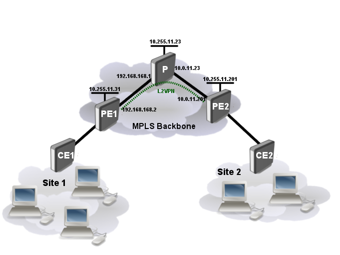
Consider network setup as ilustrated below:
We will be setting up the layer 2 connection between the CE and PE routers as well as the MPLS and L2VPN between PE routers. The layer 2 link between the CE and PE routers will be an Ethernet VLAN circuit.
Set up VLANs
CE1 and CE2 routers:
/interface vlan
  add vlan-id=600 name=vlan1 disabled=no interface=ether1
PE1 (RouterOS):
No configuration currently is needed, later we will bridge VPLS tunnel.
PE2 (JunOS):
interfaces {
    fe-0/0/1 {
        vlan-tagging;
        encapsulation vlan-ccc;
        unit 1 {
            encapsulation vlan-ccc;
            vlan-id 600;
        }
    }
}
Set up IP connection, OSPF and LDP
CE1:
/ip address add address=192.168.88.1/24 interface=vlan1
CE2:
/ip address add address=192.168.88.2/24 interface=vlan1
PE1 (RouterOS):
/interface bridge
  add name=loopback

/ip address
  add address=192.168.168.2/24 interface=ether3
  add address=10.255.11.31/32 interface=loopback

/routing ospf network
  add area=backbone disabled=no network=192.168.168.0/24
  add area=backbone disabled=no network=10.255.11.31/32

/mpls ldp
  set enabled=yes lsr-id=10.255.11.31 transport-address=10.255.11.31

/mpls ldp interface
  add interface=ether3
P (RouterOS):
/interface bridge
  add name=loopback

/ip address
  add address=10.0.11.23/24 interface=ether1
  add address=192.168.168.1/24 interface=ether2
  add address=10.255.11.23/32 interface=loopback

/routing ospf network
  add area=backbone disabled=no network=10.0.11.0/24
  add area=backbone disabled=no network=192.168.168.0/24
  add area=backbone disabled=no network=10.255.11.23/32

/mpls ldp
  set enabled=yes lsr-id=10.255.11.23 transport-address=10.255.11.23

/mpls ldp interface
  add interface=ether1
  add interface=ether2
PE2 (JunOS):
interfaces {
    fe-0/0/0 {
        unit 0 {
            family inet {
                address 10.0.11.201/24;
            }
            family mpls;
        }
    }
    lo0 {
        unit 0 {
            family inet {
                address 10.255.11.201/32;
            }
        }
    }
}

protocols {
    mpls {
        interface fe-0/0/0.0;
        interface lo0.0;

    }

    ospf {
        export [ export-connected originate ];
        area 0.0.0.0 {
            interface fe-0/0/0.0;
            interface lo0.0 {
                passive;
            }
        }
    }
    ldp {
        egress-policy connected-only;
        transport-address 10.255.11.201;
        interface all;
    }
}
Finally we need to define policy options to advertise label binding for Loopback prefix:
policy-options {
    prefix-list loopback-prefix {
        10.255.11.201/32;
    }
    policy-statement connected-only {
        from {
            prefix-list loopback-prefix;
        }
        then accept;
    }
}
Set up L2VPN
PE1 (RouterOS):
/interface vpls
  add cisco-style=yes cisco-style-id=5 name=junos-l2circuit pw-type=tagged-ethernet \
    remote-peer=10.255.11.201

/interface bridge add name=vpn
/interface bridge port
  add interface=ether5 bridge=vpn
  add interface=junos-l2circuit bridge=vpn
PE2 (JunOS):
protocol {
    l2circuit {
        neighbor 10.255.11.31 {
            interface fe-0/0/1.1 {
                virtual-circuit-id 5;
            }
        }
    }
}
Verify Operation
Verify if LDP neighbors are found and forwarding table is created:
PE1:
[admin@10.0.11.31] /mpls ldp neighbor> print
Flags: X - disabled, D - dynamic, O - operational, T - sending-targeted-hello,
V - vpls
 #      TRANSPORT       LOCAL-TRANSPORT PEER                       SEN
 0 DO   10.255.11.23    10.255.11.31    10.255.11.23:0             no
 1 DOTV 10.255.11.201   10.255.11.31    10.255.11.201:0            yes
[admin@10.0.11.31] /mpls forwarding-table> print
Flags: L - ldp, V - vpls, T - traffic-eng
 #   IN-LABEL      OUT-LABELS  DESTINATION                    I NEXTHOP
 0   expl-null
 1 L 17            3396        10.255.11.201/32               e 192.168.168.1
 2 L 19                        10.255.11.23/32                e 192.168.168.1
 3 L 23            3390        10.5.101.0/24                  e 192.168.168.1
 4 V 29                        junos-l2circuit
PE2:
juniper@J4300> show ldp neighbor
Address            Interface          Label space ID         Hold time
10.255.11.31       lo0.0              10.255.11.31:0           42
10.0.11.23         fe-0/0/0.0         10.255.11.23:0           13
Verify if L2VPN tunnel is up and running:
PE1
[admin@10.0.11.31] /interface vpls> monitor junos-l2circuit once
       remote-label: 577168
        local-label: 29
      remote-status:
          transport: 10.255.11.201/32
  transport-nexthop: 192.168.168.1
     imposed-labels: 3396,577168
PE2
juniper@J4300> show l2circuit connections
Layer-2 Circuit Connections:

Legend for connection status (St)
EI -- encapsulation invalid      NP -- interface h/w not present
MM -- mtu mismatch               Dn -- down
EM -- encapsulation mismatch     VC-Dn -- Virtual circuit Down
CM -- control-word mismatch      Up -- operational
VM -- vlan id mismatch           CF -- Call admission control failure
OL -- no outgoing label          IB -- TDM incompatible bitrate
NC -- intf encaps not CCC/TCC    TM -- TDM misconfiguration
BK -- Backup Connection          ST -- Standby Connection
CB -- rcvd cell-bundle size bad  XX -- unknown

Legend for interface status
Up -- operational
Dn -- down
Neighbor: 10.255.11.31
    Interface                 Type  St     Time last up          # Up trans
    fe-0/0/1.1(vc 5)          rmt   Up     Apr 19 12:28:30 2012           2
      Remote PE: 10.255.11.31, Negotiated control-word: No
      Incoming label: 577168, Outgoing label: 29
      Local interface: fe-0/0/1.1, Status: Up, Encapsulation: VLAN

juniper@J4300>
