SwOS: Difference between revisions
| Line 577: | Line 577: | ||
<pre>[admin@MikroTik] /file> print | <pre>[admin@MikroTik] /file> print | ||
# NAME | # NAME TYPE SIZE CREATION-TIME | ||
0 swos-1.14.lzb .lzb file 38142 | 0 swos-rb260-1.14.lzb .lzb file 38142 sep/02/2014 08:40:17</pre> | ||
* Configure TFTP server. | * Configure TFTP server. | ||
Revision as of 16:27, 30 September 2014
Summary
SwOS is an operating system designed specifically for administration of MikroTik Switch products.
SwOS is configurable from your web browser. It gives you all the basic functionality for a managed switch, plus more: allows to manage port-to-port forwarding, broadcast storm control, apply MAC filter, configure VLANs, mirror traffic, apply bandwidth limitation and even adjust some MAC and IP header fields.

Warning: Each RouterBoard switch series have their own firmware which cannot be installed on other series models! In case wrong installation is accidentally done, correct firmware has to be reinstalled following instructions from "Reinstall SwOS firmware" section below.
- RB250GS supports SwOS v1.0 and newer.
- RB260GS supports SwOS v1.7 and newer.
- RB260GSP supports SwOS v1.11 and newer.
Connecting to the Switch
Open your web browser and enter IP address of your Switch (192.168.88.1 by default) and login screen will appear.
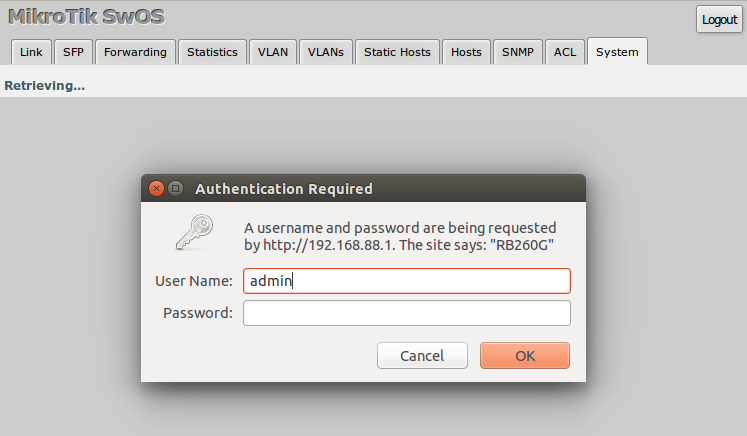
SwOS default IP address: 192.168.88.1, user name: admin and there is no password.

Note: MikroTik neighbor discovery protocol tools can be used to discover IP address of Mikrotik Switch. Manual:IP/Neighbor_discovery
Interface Overview
SwOS interface menu consists of several tabs: Link, SFP, Forwarding, Statistics, VLAN, VLANs, Static Hosts, Hosts, SNMP, ACL and System.
Description of buttons in SwOS configuration tool:
- Append - add new item to the end of the list
- Apply All - applies current configuration changes
- Cut - removes item from the list
- Clear - resets properties of the item
- Discard Changes - removes unsaved configuration
- Insert - add new item to the list (places it before current item)
- Sort - sort VLAN table by VLAN-IDs; sort host table by MAC addresses
- Change Password - changes password of the switch
- Logout - logout from current Switch
- Reboot - reboot the switch
- Reset Configuration - reset configuration back to factory defaults
- Choose File - browse for upgrade or backup file
- Upgrade - upgrade firmware of the Switch
- Restore Backup - restore Switch using selected backup file
- Save Backup - generate and download backup file from the Switch
System Tab
System Tab performs the following functions:
- General information about Switch
- Switch management
- Configuration reset
- Backup and restore configuration
- Firmware upgrade
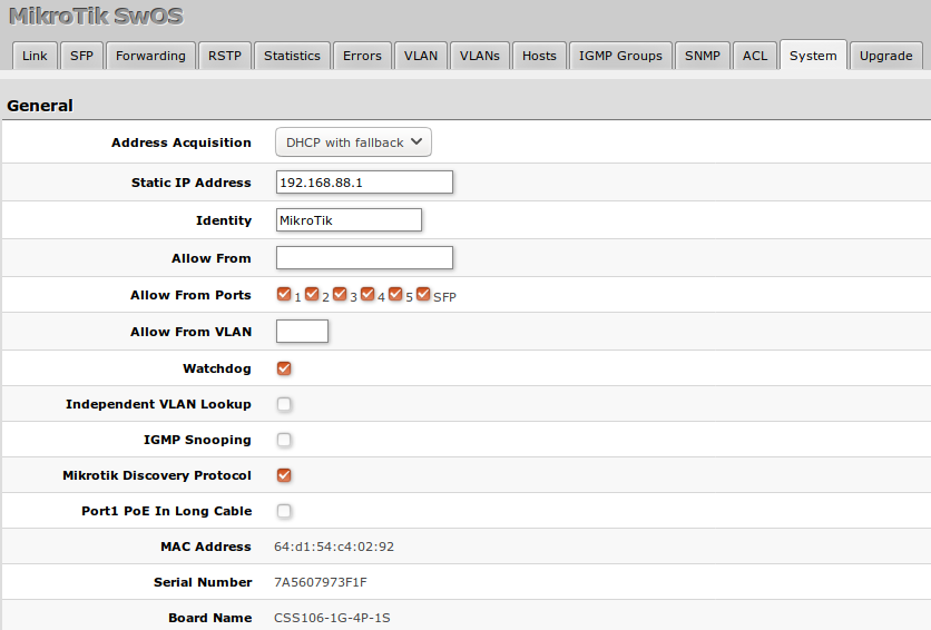

Note: SwOS uses a simple algorithm to ensure TCP/IP communication - it just replies to the same IP and MAC address packet came from. This way there is no need for Default Gateway on the device itself.
| Property | Description |
|---|---|
| IP Address | IP address of the Switch |
| Identity | Name of the Switch (for Mikrotik neighbor discovery protocol) |
| Allow From | IP address from which the service is accessible. Default value is '0.0.0.0/0' - any address |
| Allow From Ports | List of switch ports from which the service is accessible |
| Allow From VLAN | VLAN ID with which the service is accessible (VLAN Mode on ingress port must be other than disabled in order to connect)
|
| Mikrotik Discovery Protocol | Enable or disable Mikrotik neighbor discovery protocol |
| Watchdog | Enable or disable system watchdog. It will reset CPU of the switch in case of fault condition |
| MAC Address | MAC address of the Switch (Read-only) |
| Version | Firmware version of the Switch |
| Uptime | Current Switch uptime |
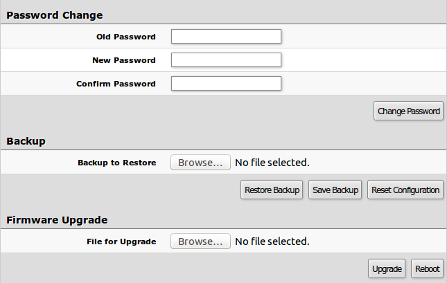
Firmware Upgrade
Firmware can be upgraded/downgraded by selecting firmware file and pressing upgrade button. Switch will reboot automatically after successful upgrade.
PoE and Health (RB260GSP)

| Property | Description |
|---|---|
| Port1 PoE In Long Cable | If enabled, it will turn off short detection on all PoE out ports to allow use of longer ethernet cables. This is potentially dangerous setting and should be used with caution. |
| Voltage | Shows the input voltage measured in volts |
| Temperature | Shows PCB temperature in celsius temperature scale |
Link Tab
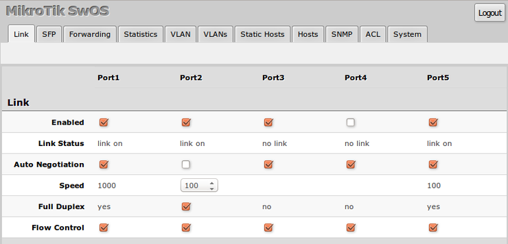
Link Tab allows you to:
- Configure Ethernet ports
- Monitor status of Ethernet ports
| Property | Description |
|---|---|
| Enabled | Enable or disable port |
| Link Status | Current link status (Read-only) |
| Auto Negotiation | Enable or disable auto negotiation |
| Speed | Specify speed setting of the port (requires auto negotiation to be disabled) |
| Full Duplex | Specify duplex mode of the port (requires auto negotiation to be disabled) |
| Flow control | Enable or disable 802.3x Flow control |
PoE (RB260GSP)
PoE settings configure Power over Ethernet output on RB260GSP port2-port5 and show PoE status and measurements.

| Property | Description |
|---|---|
| PoE Out |
Sets PoE out mode of the port:
|
| PoE Priority | Port priority for PoE out supply. If installation is going over power budged, port with the lowest priority is going to be turned off first. 1 - the highest priority port; 4 - the lowest priority port |
| PoE Status |
Current PoE out status of the port:
|
| PoE Current | Shows current usage on the port measured in miliamperes |
| PoE Power | Shows PoE out power on the port measured in watts |
SFP Tab (RB260GS/RB260GSP)
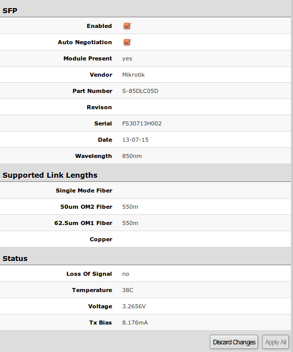
SFP Tab allows you to:
- Configure SFP port
- Monitor status of SFP port
| Property | Description |
|---|---|
| Enabled | Enable or disable SFP port |
| Auto Negotiation | Enable or disable auto negotiation of SFP port (some SFP modules may required it disabled in order to work) |
Forwarding Tab
Forwarding Tab provides advanced forwarding options among switch ports, port locking, port mirroring, bandwidth limit and broadcast storm control features.
On RB260 series switches ingress rate per port as well as rate for broadcast traffic can be configured with Access Control List by setting Rate. ACL must have one port per entry to provide bandwidth limiting properly.
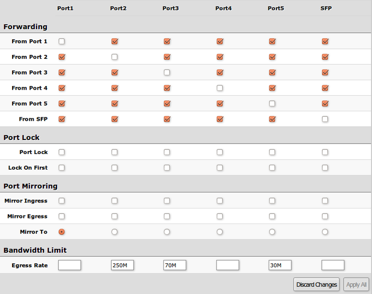
| Property | Description |
|---|---|
| Forwarding | Forwarding table - allows or restricts traffic flow between specific ports |
| Port Lock |
|
| Port Mirroring |
|
| Bandwidth Limit |
|
| Broadcast Storm Control |
|
Statistics Tab
Provides detailed information about received and transmitted packets.
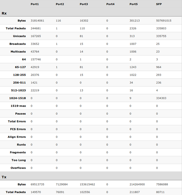
Packet Flow
Packet processing in SwOS is described here: Atheros8316 packet flow diagram
VLAN Tab
VLAN configuration for Switch ports.
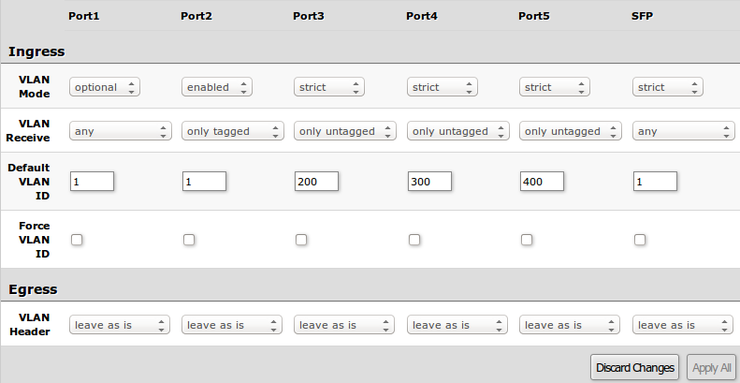
| Property | Description |
|---|---|
| VLAN Mode |
VLAN mode for ingress port:
|
| VLAN Receive | Defines the type of allowed packets on ingress port: any / only tagged / only untagged (only supported on RB260GS) |
| Default VLAN ID | Switch will treat untagged ingress packets as they are tagged with this VLAN ID. VLAN tag itself will be added only if there is VLAN Header = add if missing specified on egress port |
| Force VLAN ID | Whether to apply Default VLAN ID to incoming packets with VLAN tag |
| VLAN Header |
|

Note: VLAN modes enabled and strict require VLAN ID 1 in VLANs table to allow access of untagged traffic to switch itself.
Example
VLANs Tab
VLAN tables specifies certain forwarding rules for packets that have specific 802.1q tag. Basically the table contains entries that map specific VLAN tag IDs to a group of one or more ports. Packets with VLAN tags leave switch through one or more ports that are set in corresponding table entry. VLAN table works together with destination MAC lookup to determine egress ports. VLAN table supports up to 4096 entries.
RB250GS VLANs tab

| Property | Description |
|---|---|
| VLAN ID | VLAN ID of the packet |
| Ports | Ports the packet should be mapped to |
RB260GS VLANs tab

| Property | Description |
|---|---|
| VLAN ID | VLAN ID of the packet |
| Ports | Each port has individual VLAN header options for each VLAN ID. Depending on VLAN mode if lookup is done in this table, egress action of packets is processed by this option. Egress option from VLAN tab is ignored. |
Hosts Tab
This table represents dynamically learnt MAC address to port mapping entries. When Switch receives a packet from certain port, it adds the packets source MAC address X and port it received the packet from to host table, so when a packet comes in with destination MAC address X it knows to which port it should forward the packet. If the destination MAC address is not present in host table then it forwards the packet to all ports in the group. Dynamic entries take about 5 minutes to time out.

| Property | Description |
|---|---|
| Ports | Ports the packet should be forwarded to (Read-only) |
| MAC | Learned MAC address (Read-only) |
| VLAN ID | Learned VLAN ID (Read-only) (only supported on RB260GS/RB260GSP) |
Static Hosts Tab
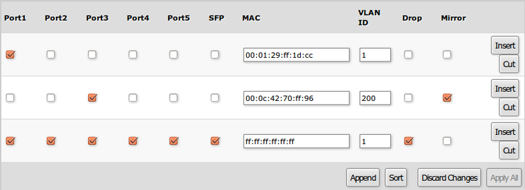
Static host table entries. Static entries will take over dynamic if dynamic entry with same mac-address already exists. Also by adding a static entry you get access to some more functionality.
| Property | Description |
|---|---|
| Ports | Ports the packet should be forwarded to |
| MAC | MAC address |
| VLAN ID | VLAN ID (only supported on RB260GS/RB260GSP) |
| Drop | Packet with certain MAC address coming from certain ports can be dropped |
| Mirror | Packet can be cloned and sent to mirror-target port |
ACL Tab
An access control list (ACL) rule table is very powerful tool allowing wire speed packet filtering, forwarding and VLAN tagging based on L2,L3 protocol header field conditions. SwOS allow you to implement limited number of access control list rules (32 simple rules (only L2 conditions are used); 16 rules where both L2 and L3 conditions are used; or 8 advanced rules where all L2,L3 and L4 conditions are used).
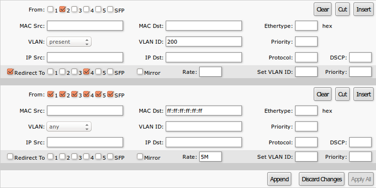
Each rule contains a conditions part and an action part.
Conditions part parameters
| Property | Description |
|---|---|
| From | Port that packet came in from |
| MAC Src | Source MAC address and mask |
| MAC Dst | Destination MAC address and mask |
| Ethertype | Protocol encapsulated in the payload of an Ethernet Frame |
| VLAN |
VLAN header presence:
|
| VLAN ID | VLAN tag ID |
| Priority | Priority in VLAN tag |
| IP Src (IP/netmask:port) | Source IP address, netmask and L4 port number |
| IP Dst (IP/netmask:port) | Destination IP address, netmask and L4 port number |
| Protocol | IP protocol |
| DSCP | IP DSCP field |
Action part parameters
| Property | Description |
|---|---|
| Redirect To | Whether to force new destination ports (If Redirect To is enabled and no ports specified in Redirect To Ports, packet will be dropped ) |
| Redirect To Ports | Destination ports for |
| Mirror | Clones packet and sends it to mirror-target port |
| Rate | Limits bandwidth (bps) (only supported on RB260GS/RB260GSP) |
| Set VLAN ID | Changes the VLAN tag ID, if VLAN tag is present |
| Priority | Changes the VLAN tag priority bits, if VLAN tag is present |
SNMP Tab
SNMP Tab consists of settings to monitor the Switch remotely.
Available SNMP data:
System informationSystem uptimePort statusInterface statistics

| Property | Description |
|---|---|
| Enabled | Enable or disable SNMP service |
| Community | SNMP community name |
| Contact Info | Contact information for the NMS |
| Location | Location information for the NMS |
Reset
There are two ways to reset the device to defaults:
Reset button
The only button on the SwOS device. It has two functions:
- Hold this button during boot time until LED light starts flashing, release the button to reset SwOS configuration (same result as with reset hole)
- Hold this button during boot time longer, until LED starts to bling twice as fast, and then release it to make the device wait for TFTP firmware upgrade
Jumper reset hole
Located on the bottom of case, behind one of the rubber feet of all SwOS devices – resets SwOS software to defaults. Must short circuit the metallic sides of the hole (with a screwdriver, for example) and boot the device. Hold screwdriver in place until SwOS configuration is cleared.
Reinstall SwOS firmware
It is possible to upload and install SwOS firmware using BOOTP. This example shows how to reinstall SwOS using RouterOS.

Warning: Each RouterBoard switch series have their own firmware which cannot be installed on other series models! In case wrong installation is accidentally done, correct firmware has to be reinstalled following these instructions.
- RB250GS supports SwOS v1.0 and newer.
- RB260GS supports SwOS v1.7 and newer.
- RB260GSP supports SwOS v1.11 and newer.
- Configure IP address and DHCP server with BOOTP enabled on the installation router.
/ip address
add address=10.0.0.1/24 interface=ether1
/ip pool
add name=dhcp_pool1 ranges=10.0.0.2-10.0.0.254
/ip dhcp-server
add interface=ether1 address-pool=dhcp_pool1 bootp-support=dynamic disabled=no
/ip dhcp-server network
add address=10.0.0.0/24 gateway=10.0.0.1
- Upload new SwOS firmware file to the router filesystem.
[admin@MikroTik] /file> print
 # NAME                     TYPE           SIZE                 CREATION-TIME
 0 swos-rb260-1.14.lzb     .lzb file        38142              sep/02/2014 08:40:17
- Configure TFTP server.
/ip tftp
add ip-addresses=10.0.0.0/24 real-filename=swos-rb260-1.14.lzb read-only=yes allow=yes
- Hold the RESET button of the switch when starting it.
- After few seconds ACT LED will start blinking. Wait till ACT LED blinks twice as fast and release RESET button.
- Make ethernet connection between the switch Port1 and ethernet port you configured DHCP server on. After few seconds new firmware should be successfully uploaded and installed.