Manual:Simple BGP Multihoming: Difference between revisions
No edit summary |
No edit summary |
||
| Line 1: | Line 1: | ||
{{Versions|all}} | {{Versions|all}} | ||
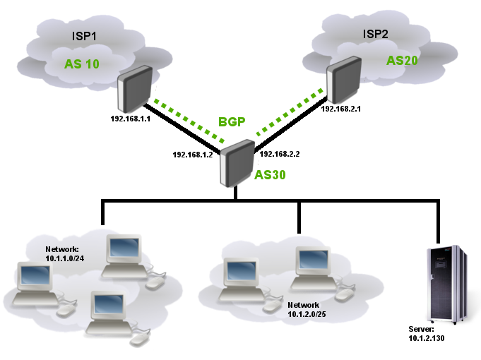
Ilustration below shows simple multihomed BGP setup. This setup can be used for load sharing between ISPs or one ISP as main and other ISP as backup link. | |||
[[File:bgp-multihoming.png]] | [[File:bgp-multihoming.png]] | ||
Lets say that local Internet registry assigned to us two /24 networks: '''10.1.1.0/24''' and '''10.1.2.0/24''' and our AS is 30 (Private AS cannot be used in such setups). | |||
First network entirely is used for workstations in our corporate network. Part of the other network is also used for workstation and another part is reserved for server. At this point our company has only one server with address 10.1.2.130 | |||
The goal is advertise our assigned networks to BGP peers and use only one provider as main link, ISP2 link is for backup only. | |||
{{Note | This example does not show how to provide connectivity between core router, local networks and servers }} | |||
Revision as of 16:45, 1 November 2010
Ilustration below shows simple multihomed BGP setup. This setup can be used for load sharing between ISPs or one ISP as main and other ISP as backup link.
Lets say that local Internet registry assigned to us two /24 networks: 10.1.1.0/24 and 10.1.2.0/24 and our AS is 30 (Private AS cannot be used in such setups). First network entirely is used for workstations in our corporate network. Part of the other network is also used for workstation and another part is reserved for server. At this point our company has only one server with address 10.1.2.130
The goal is advertise our assigned networks to BGP peers and use only one provider as main link, ISP2 link is for backup only.

Note: This example does not show how to provide connectivity between core router, local networks and servers
[ Top | Back to Content ]

