Manual:Packet Flow: Difference between revisions

From MikroTik Wiki
Jump to navigation Jump to search
Line 47: Line 47:


|-
|-
|[[Image:Input_interface.jpg|Input Interface|100px]]
|[[Image:Physical_in_interface.png|Input Interface|100px]]
|Starting point in packets way through the router facilities. It does not matter what interface (physical or virtual) packet is received it will start its way from here
|Starting point in packets way through the router facilities. Packet is received it will start its way from here.


|-
|-
|[[Image:output_interface.jpg|Output Interface|100px]]
|[[Image:Physical_out_interface.png|Output Interface|100px]]
|Last point in packets way through the router facilities. Just before the packet is actually sent out.
|Last point in packets way through the router facilities. Just before the packet is actually sent out.
|-
|[[Image:Logical_in_interface.png|Input Interface|100px]]
|Intermediate interface where packet continues to process through the device after decapsulation
|-
|[[Image:Logical_out_interface.png |Output Interface|100px]]
|Intermediate interface where packet continue to process through the device before encapsulation


|-
|-
Line 62: Line 70:
|Starting point for packets generated by router itself
|Starting point for packets generated by router itself
|}
|}
===Configurable Facilities===


Revision as of 12:23, 8 January 2019

Applies to RouterOS: v6.0+

Overview

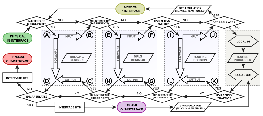
MikroTik RouterOS is designed to be easy to operate in various aspects of network configuration. Therefore creating limitation for individual IP or NATting internal clients to a public address or Hotspot configuration can be done without the knowledge about how the packets are processed in the router - you just go to corresponding menu and create necessary configuration.

However more complicated tasks, such as traffic prioritization, routing policies, where it is necessary to utilize more than one RouterOS facility, requires knowledge: How these facilities work together? What happens when and why?

To address these questions we created a packet flow diagram.

Diagrams

For MikroTik RouterOS v6.0 was created detailed diagrams to ease understanding of packet flow.

Overall Packetflow Diagram
Packet Flow Diagram
Packet Flow Diagram

Bridging Diagram

Bridging Diagram
Bridging Diagram
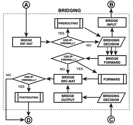
In this subsection you can inspect how packet are going through the bridge. For example, if you configure /interface bridge settings set use-ip-firewall=yes, then packet will go through the one of three predefined ip firewall chains: prerouting, forward, postrouting.

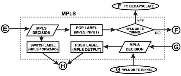
MPLS Diagram

Packet-forwarding decisions are made solely on the contents of this label, without the need to examine the packet itself. Diagram describe MPLS label movement in RouterOS.
MPLS Diagram
MPLS Diagram

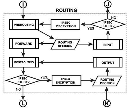
Routing Diagram

Routing Diagram
Routing Diagram
Each routing protocol (except BGP) has it's own internal tables. This is where per-protocol routing decisions are made. BGP does not have internal routing tables and stores complete routing information from all peers in the RIB. RIB contains routes grouped in separate routing tables based on their value of routing-mark. All routes without routing-mark are kept in the main routing table. These tables are used for best route selection. The main table is also used for nexthop lookup.

Packet Flow Chains

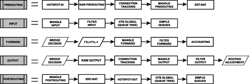
This diagram explains in detail each section of the Overall Packetflow Diagram.
Packet Flow Chains
Packet Flow Chains

Diagram Analaysis

Basic Concepts

Image Explanation
Input Interface Starting point in packets way through the router facilities. Packet is received it will start its way from here.
Output Interface Last point in packets way through the router facilities. Just before the packet is actually sent out.
Input Interface Intermediate interface where packet continues to process through the device after decapsulation
Output Interface Intermediate interface where packet continue to process through the device before encapsulation
Local Process IN Last point in packets way to router itself, after this packet is discarded
Local Process OUT Starting point for packets generated by router itself

Configurable Facilities

Each and every facilities in this section corresponds with one particular menu in RouterOS. Users are able to access those menu and configure these facilities directly

Image RouterOS CLI
Connection Tracking /ip firewall connection tracking
Filter Input /ip firewall filter
Filter Forward /ip firewall filter
Filter Output /ip firewall filter
Source NAT /ip firewall nat
Destination NAT /ip firewall nat
Mangle Prerouting /ip firewall mangle
Mangle Input /ip firewall mangle
Mangle Forward /ip firewall mangle
Mangle Output /ip firewall mangle
Mangle Postrouting /ip firewall mangle
Global-in HTB /queue simple and /queue tree
Global-Out HTB /queue simple and /queue tree
Interface HTB /queue simple and /queue tree
IPSec_Policy /ip ipsec policy
Accounting /ip accounting
Use IP Firewall /interface bridge settings
Bridge Input /interface bridge filter
Bridge Forward /interface bridge filter
Bridge Output /interface bridge filter
Bridge Destination NAT /interface bridge nat
Bridge Source NAT /interface bridge nat

Automated processes and decisions

Image Description
In-interface Bridge Check if the actual input interface is a port for bridge OR checks if input interface is bridge
Hotspot In Allow to capture traffic witch otherwise would be discarded by connection tracking - this way our Hotspot feature are able to provide connectivity even if networks settings are in complete mess
Bridge Decision Bridge goes through the MAC address table in order to find a match to destination MAC address of packet. When match is found - packet will be send out via corresponding bridge port. In case of no match - multiple copies of packet will be created and packet will be sent out via all bridge ports
Bridge Decision This is a workaround, allows to use "out-bridge-port" before actual bridge decision.
Routing Decision Router goes through the route n order to find a match to destination IP address of packet. When match is found - packet will be send out via corresponding port or to the router itself . In case of no match - packet will be discarded.
Routing Adjustment This is a workaround that allows to set-up policy routing in mangle chain output
TTL Adjustment Indicates exact place where Time To Live (TTL) of the routed packet is reduced by 1. If it become 0 packet will be discarded
IPSec_Decryption Self explanatory
IPSec_Encryption Self explanatory
Out-interface Bridge Check if the actual output interface is a port for bridge OR checks if output interface is bridge
Hotspot Out Undo all that was done by hotspot-in for the packets that is going back to client.


Examples

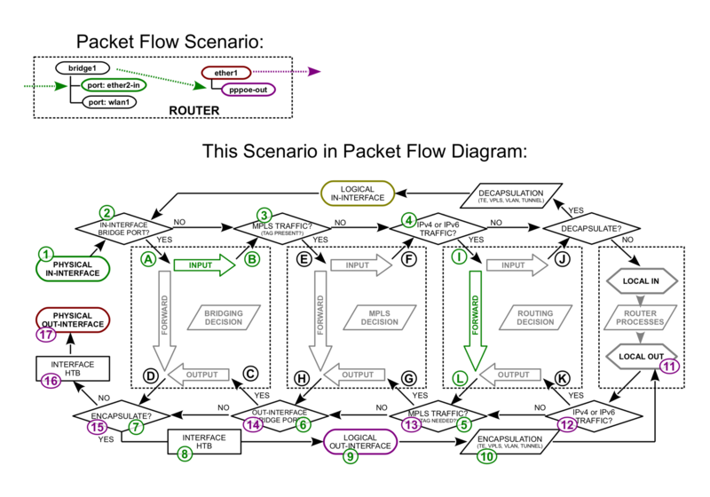
In this subsection you can overview different protocol packet processing in RouterOS.

Bridge port in with PPPoE-out
Example 1
Example 1

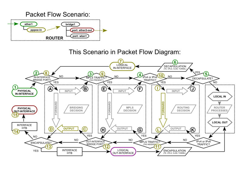
PPPoE-in with bridge port out

Example 2
Example 2

Vlan Untagging/Tagging in the bridge interface
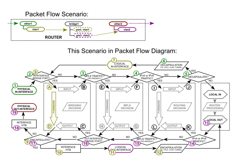
Example 3
Example 3

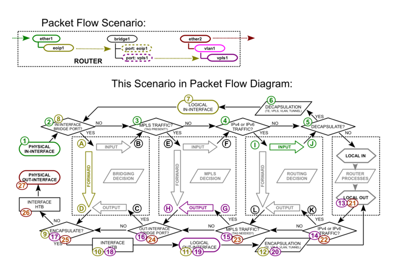
EoIP with VPLS out

Example 4
Example 4

IPsec Encryption/Decryption

Internet Protocol Security (IPsec) is a set of protocols defined by the Internet Engineering Task Force (IETF) to secure packet exchange over unprotected IP/IPv6 networks such as Internet.
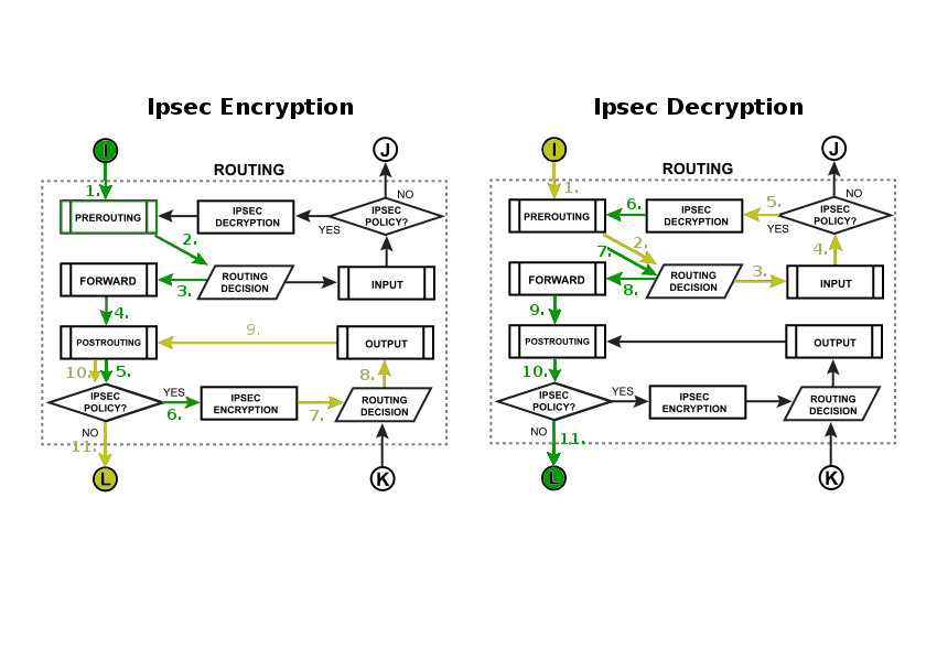
Example 5
Example 5