Manual:Packet Flow: Difference between revisions
No edit summary |
No edit summary |
||
| Line 20: | Line 20: | ||
[[Image:Input_interface.jpg|Input Interface|100px]] | |||
[[Image:output_interface.jpg|Output Interface|100px]] | |||
[[Image:local_process-_in.jpg|Filter Output|100px]] | |||
[[Image:local_process-_out.jpg|Filter Output|100px]] | |||
[[Image:Filter_input.jpg|Filter Input|100px]] | |||
[[Image:Filter_forward.jpg|Filter Forward|100px]] | |||
[[Image:Filter_output.jpg|Filter Output|100px]] | |||
[[Image:src_nat.jpg|Source NAT|100px]] | |||
[[Image:dst_nat.jpg|Destination NAT|100px]] | |||
[[Image:connection_tracking.jpg|Connection Tracking|100px]] | |||
[[Image:hotspot_in.jpg|Hotspot In|100px]] | |||
[[Image:Hotspot_out.jpg|Hotspot Out|100px]] | |||
[[Image:mangle_prerouting.jpg|Mangle Prerouting|100px]] | [[Image:mangle_prerouting.jpg|Mangle Prerouting|100px]] | ||
| Line 27: | Line 48: | ||
[[Image:mangle_output.jpg|Mangle Output|100px]] | [[Image:mangle_output.jpg|Mangle Output|100px]] | ||
[[Image:mangle_postrouting.jpg|Mangle Postrouting|100px]] | [[Image:mangle_postrouting.jpg|Mangle Postrouting|100px]] | ||
[[Image:global_in.jpg|Global-in HTB|100px]] | |||
[[Image:global_out.jpg|Global-Out HTB|100px]] | |||
[[Image:Interface HTB.jpg|Interface HTB|100px]] | |||
[[Image:accounting.jpg|Accounting|100px]] | |||
[[Image:TTL=TTL-1.jpg|TTL Adjustment|100px]] | |||
[[Image:use_ip_firewall.jpg|Use IP Firewall|100px]] | |||
[[Image:routing_adjustment.jpg|Routing Adjustment|100px]] | |||
[[Image:Bridge_forward.jpg|Bridge Forward|100px]] | |||
[[Image:bridge_input.jpg|Bridge Input|100px]] | |||
[[Image:Bridge_output.jpg|Bridge Output|100px]] | |||
[[Image:Bridge Desicion.jpg|Bridge Decision|100px]] | |||
[[Image:bridge_decision.jpg|Bridge Decision|100px]] | |||
[[Image:Bridge_dst_nat.jpg.jpg|Bridge Destination NAT|100px]] | |||
[[Image:Bridge_src_nat.jpg|Bridge Source NAT|100px]] | |||
[[Image:In-interface-bridge.jpg|In-interface Bridge|100px]] | |||
[[Image:out_interface_bridge.jpg|Out-interface Bridge|100px]] | |||
[[Image:IPSec_Decryption.jpg|IPSec_Decryption|100px]] | |||
[[Image:IPSec_Encryption.jpg|IPSec_Encryption|100px]] | |||
[[Image:IPsec_policy.jpg|IPSec_Policy|100px]] | |||
==Analysis== | ==Analysis== | ||
Revision as of 16:00, 27 November 2008
MikroTik RouterOS is designed to be easy to operate in various aspects of network configuration. Therefore creating limitation for individual IP or natting internal clients to a public address or Hotspot configuration can be done without the knowledge about how the packets are processed in the router - you just go to corresponding menu and create necessary configuration.
However more complicated tasks, such as traffic prioritization, routing policies, where it is necessary to utilize more than one RouterOS facility, requires knowledge: How these facilities work together? What happens when and why?
To address these questions we created a packet flow diagram.
Diagram
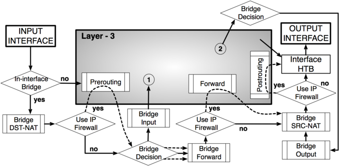
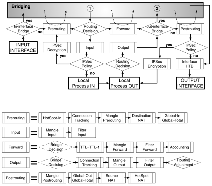
As it was impossible to get everything in one diagram, Packet flow diagram for Mikrotik RouterOS v3.x was created in 2 parts:
- Bridging or Layer-2 (MAC) where Routing part is simplified to one "Layer-3" box
- Routing or Layer-3 (IP) where Bridging part is simplified to one "Bridging" box

