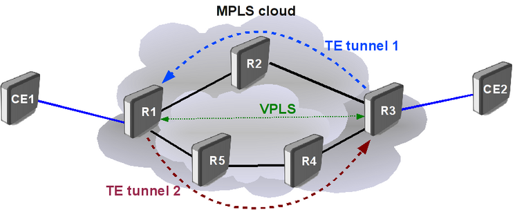
Manual:TE Tunnels Example
Introduction
Application example
Consider following setup:
IP Connectivity and LDP
R1
ether1 connects to R2, ether2 connects to R5
/system identity set name=R1

/interface bridge add name=lo0

/ip address
add address=192.168.55.1/30 interface=ether1
add address=192.168.55.18/30 interface=ether2
add address=10.255.1.1/32 interface=lo0


/routing ospf instance
set default router-id=10.255.1.1

/routing ospf networks
add network=192.168.55.0/24 area=backbone
add network=10.255.1.0/24 area=backbone

/mpls ldp
set enabled=yes lsr-id=10.255.1.1 transport-address=10.255.1.1

/mpls ldp interface
add interface=ether1
add interface=ether2
R2
ether1 connects to R1, ether2 connects to R3
/system identity set name=R2

/interface bridge add name=lo0

/ip address
add address=192.168.55.2/30 interface=ether1
add address=192.168.55.5/30 interface=ether2
add address=10.255.1.2/32 interface=lo0


/routing ospf instance
set default router-id=10.255.1.2

/routing ospf networks
add network=192.168.55.0/24 area=backbone
add network=10.255.1.0/24 area=backbone

/mpls ldp
set enabled=yes lsr-id=10.255.1.2 transport-address=10.255.1.2

/mpls ldp interface
add interface=ether1
add interface=ether2
R3
ether1 connects to R2, ether2 connects to R4
/system identity set name=R3

/interface bridge add name=lo0

/ip address
add address=192.168.55.6/30 interface=ether1
add address=192.168.55.9/30 interface=ether2
add address=10.255.1.3/32 interface=lo0


/routing ospf instance
set default router-id=10.255.1.3

/routing ospf networks
add network=192.168.55.0/24 area=backbone
add network=10.255.1.0/24 area=backbone

/mpls ldp
set enabled=yes lsr-id=10.255.1.3 transport-address=10.255.1.3

/mpls ldp interface
add interface=ether1
add interface=ether2
R4
ether1 connects to R3, ether2 connects to R5
/system identity set name=R4

/interface bridge add name=lo0

/ip address
add address=192.168.55.10/30 interface=ether1
add address=192.168.55.13/30 interface=ether2
add address=10.255.1.4/32 interface=lo0


/routing ospf instance
set default router-id=10.255.1.4

/routing ospf networks
add network=192.168.55.0/24 area=backbone
add network=10.255.1.0/24 area=backbone

/mpls ldp
set enabled=yes lsr-id=10.255.1.4 transport-address=10.255.1.4

/mpls ldp interface
add interface=ether1
add interface=ether2
R5
ether1 connects to R4, ether2 connects to R1
/system identity set name=R5

/interface bridge add name=lo0

/ip address
add address=192.168.55.14/30 interface=ether1
add address=192.168.55.17/30 interface=ether2
add address=10.255.1.5/32 interface=lo0


/routing ospf instance
set default router-id=10.255.1.5

/routing ospf networks
add network=192.168.55.0/24 area=backbone
add network=10.255.1.0/24 area=backbone

/mpls ldp
set enabled=yes lsr-id=10.255.1.5 transport-address=10.255.1.5

/mpls ldp interface
add interface=ether1
add interface=ether2
After OSPF and LDP setup ensure that ospf is working properly
[admin@R1] /routing ospf neighbor> print
 0 instance=default router-id=10.255.1.5 address=192.168.55.17 interface=ether2
   priority=1 dr-address=192.168.55.17 backup-dr-address=192.168.55.18
   state="Full" state-changes=5 ls-retransmits=0 ls-requests=0 db-summaries=0
   adjacency=32m17s

 1 instance=default router-id=10.255.1.2 address=192.168.55.2 interface=ether1
   priority=1 dr-address=192.168.55.2 backup-dr-address=192.168.55.1
   state="Full" state-changes=5 ls-retransmits=0 ls-requests=0 db-summaries=0
   adjacency=32m17s
[admin@R1] /routing ospf neighbor>
[admin@R1] /ip route> print
Flags: X - disabled, A - active, D - dynamic,
C - connect, S - static, r - rip, b - bgp, o - ospf, m - mme,
B - blackhole, U - unreachable, P - prohibit
 #      DST-ADDRESS        PREF-SRC        GATEWAY            DISTANCE
 0 ADS  0.0.0.0/0                          10.1.101.1         0
 1 ADC  10.1.101.0/24      10.1.101.9      ether3             0
 2 ADC  10.255.1.1/32      10.255.1.1      lo0                0
 3 ADo  10.255.1.2/32                      192.168.55.2       110
 4 ADo  10.255.1.3/32                      192.168.55.2       110
 5 ADo  10.255.1.4/32                      192.168.55.17      110
 6 ADo  10.255.1.5/32                      192.168.55.17      110
 7 ADC  192.168.55.0/30    192.168.55.1    ether1             0
 8 ADo  192.168.55.4/30                    192.168.55.2       110
 9 ADo  192.168.55.8/30                    192.168.55.2       110
                                           192.168.55.17
10 ADo  192.168.55.12/30                   192.168.55.17      110
11 ADC  192.168.55.16/30   192.168.55.18   ether2             0
[admin@R1] /ip route>
Also make sure MPLS forwarding-table has label bindings
[admin@R1] /mpls forwarding-table> print
Flags: L - ldp, V - vpls, T - traffic-eng
 #   IN-LABEL      OUT-LABELS  DESTINATION                    I NEXTHOP
 0   expl-null
 1 L 16                        10.255.1.5/32                  e 192.168.55.17
 2 L 17            19          192.168.55.8/30                e 192.168.55.2
 3 L 18            19          10.255.1.4/32                  e 192.168.55.17
 4 L 19            21          10.255.1.3/32                  e 192.168.55.2
 5 L 20                        192.168.55.12/30               e 192.168.55.17
 6 L 21                        192.168.55.4/30                e 192.168.55.2
 7 L 22                        10.255.1.2/32                  e 192.168.55.2
VPLS tunnel
ether4 goes to CE routers
R1
/interface bridge add name=vpn

/interface vpls
add remote-peer=10.255.1.3 vpls-id=3:3

/interface bridge port
add interface=ether4 bridge=vpn
add interface=vpls1 bridge=vpn
R3
/interface bridge add name=vpn

/interface vpls
add remote-peer=10.255.1.1 vpls-id=3:3

/interface bridge port
add interface=ether4 bridge=vpn
add interface=vpls1 bridge=vpn
Make sure that VPLS tunnel is established and running
[admin@R1] /interface vpls> monitor 0 once
       remote-label: 23
        local-label: 23
      remote-status:
          transport: 10.255.1.3/32
  transport-nexthop: 192.168.55.2
     imposed-labels: 21,23

[admin@R1] /interface vpls>
TE Support
Traffic engineering needs RSVP protocol enabled on head end, tail end and forwarding routers. And additional setup to use CSPF.
In our example all routers have the same configuration:
# set up CSPF
/routing ospf instance
set default mpls-te-area=backbone mpls-te-router-id=lo0

# add interfaces on which to run RSVP
/mpls traffic-eng interface
add interface=ether1 bandwidth=10Mbps
add interface=ether2 bandwidth=10Mbps
TE Tunnels
Secondary path
Reoptimization
