Manual:VRRP-examples: Difference between revisions
Jump to navigation
Jump to search
No edit summary |
No edit summary |
||
| Line 6: | Line 6: | ||
[[Image:vrrp-basic.png|Basic VRRP example |400px|Basic VRRP example ]] | [[Image:vrrp-basic.png|Basic VRRP example |400px|Basic VRRP example ]] | ||
<p> | <p> | ||
This is the basic VRRP configuration example | This is the basic VRRP configuration example.<br/> | ||
According to this configuration, as long as the master, R1, is functional, all traffic destined to the external network gets directed to R1. But as soon as R1 fails, R2 takes over as the master and starts handling packets forwarded to the interface associated with IP(R1). In this setup Router R2 is completely idle during Backup period. | |||
According to this configuration, as long as the master, R1, is functional, all traffic destined to the external network gets directed to R1. But as soon as R1 fails, R2 takes over as the master and starts handling packets forwarded to the interface associated with IP(R1). | </p> | ||
<h4>Configuration</h4> | |||
<p> | |||
R1 configuration: | |||
<pre> | |||
/ip address add address=192.168.1.1/24 interface=ether1 | |||
/interface vrrp add interface=ether1 vrid=49 priority=255 | |||
/ip address add address=192.168.1.1/32 interface=vrrp1 | |||
</pre> | |||
R2 configuration: | |||
<pre> | |||
/ip address add address=192.168.1.2/24 interface=ether1 | |||
/interface vrrp add interface=ether1 vrid=49 | |||
/ip address add address=192.168.1.1/32 interface=vrrp1 | |||
</pre> | |||
</p> | |||
<h4>Testing</h4> | |||
<p> | |||
</p> | </p> | ||
Revision as of 11:22, 3 October 2008
VRRP Configuration Examples
This section contains several useful VRRP configuration examples
Basic Setup
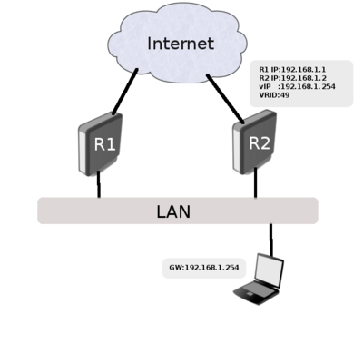
This is the basic VRRP configuration example.
According to this configuration, as long as the master, R1, is functional, all traffic destined to the external network gets directed to R1. But as soon as R1 fails, R2 takes over as the master and starts handling packets forwarded to the interface associated with IP(R1). In this setup Router R2 is completely idle during Backup period.
Configuration
R1 configuration:
/ip address add address=192.168.1.1/24 interface=ether1
/interface vrrp add interface=ether1 vrid=49 priority=255
/ip address add address=192.168.1.1/32 interface=vrrp1
R2 configuration:
/ip address add address=192.168.1.2/24 interface=ether1
/interface vrrp add interface=ether1 vrid=49
/ip address add address=192.168.1.1/32 interface=vrrp1
Testing
Load sharing

